Timer

The source’s ClockInit function focuses on configurations:
PLL multiplication factor = 9
Flash Latency = 2
APB low-speed prescaler (APB1) = 2
Link: https://github.com/ngminhthanh12a3/DESLabSTM32Training_TIMER/blob/main/Src/main.c#L52-L132
Timer Configuration
This training material illustrated a Timer Configuration to create a 1000-milisecond delay for blinking LED0. \(\mu s\)- and \(ms\)-level delay functions are provided from settings of TIM1 block.
The APB2 is set to 72MHz (\(f_{CK\_PSC}\)). Prescaler configures counter clock frequency \(CK\_CNT\) working at 1MHz. The Prescaler (PSC) is calculated as follows:

Enable TIM1 timer clock

Fig. 19 APB2 peripheral clock enable register (RCC_APB2ENR) (Source: [[STM32_RM0008], page 112])
// Bit 11 TIM1EN: TIM1 timer clock enable
RCC->APB2ENR |= (1 << 11); // TIM1 timer clock enabled
Set Prescaler value

Fig. 20 TIMx prescaler (TIMx_PSC) (Source: [[STM32_RM0008], page 418])
// Bits 15:0 PSC[15:0]: Prescaler value
TIM1->PSC = 72 - 1;
Set Auto-reload value

Fig. 21 TIMx auto-reload register (TIMx_ARR) (Source: [[STM32_RM0008], page 419])
// Bits 15:0 ARR[15:0]: Auto-reload value
TIM1->ARR = 0xffff - 1;
Enable couter

Fig. 22 TIM1 and TIM8 control register 1 (TIMx_CR1) (Source: [[STM32_RM0008], page 338])
// Bit 0 CEN: Counter enable
TIM1->CR1 |= (1 << 0); // Counter enabled
Check update interrupt flag
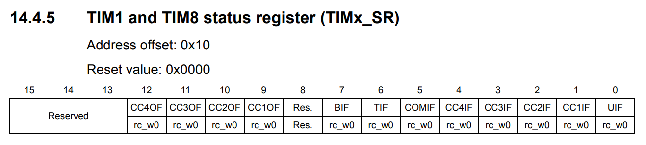
Fig. 23 TIM1 and TIM8 status register (TIMx_SR) (Source: [[STM32_RM0008], page 346])
// Bit 0 UIF: Update interrupt flag
while(!(TIM1->SR & (1 << 0)));
Full Implementation Source
Link: https://github.com/ngminhthanh12a3/DESLabSTM32Training_TIMER/blob/main/Src/main.c